Pump Affinity Laws and VFD Speed Control: How to Calculate Flow, Head & Energy Savings
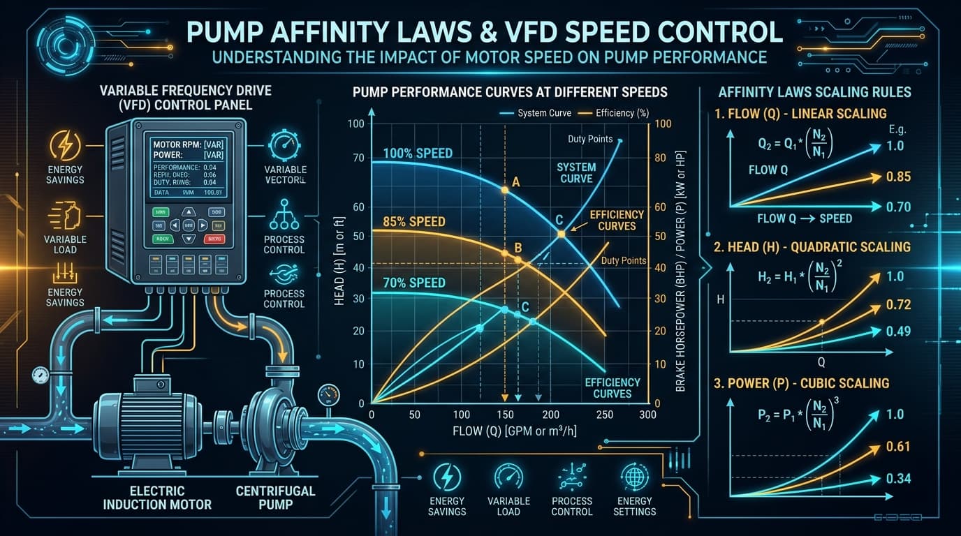
Figure 1: Mathematical scaling relationships of pump rotational speed (RPM) against volumetric flow (linear), developed dynamic head (quadratic), and shaft power (cubic).
Why This Matters for Plant Operators
In industrial facilities, electric motors driving pumps account for over 25% of total plant electricity consumption. The pump affinity laws mathematically prove that shaft power drops with the cube of motor rotational speed. Slowing down a motor by just 20% slashes consumed electrical power by nearly 50%!
1. What Are the Pump Affinity Laws? Simple Explanation
The affinity laws (also termed the hydrodynamic similarity laws) are mathematical relationships that predict how a centrifugal pump will perform when you adjust its rotational speed (N) or its impeller outside diameter (D).
They are rooted in the physical principle of geometric, kinematic, and dynamic similarity. Simply stated: as long as the fluid flow geometry inside the impeller passages remains proportional, fluid velocity triangles scale linearly with blade peripheral tip speed.
Model Dynamic H-Q Operating Points Live
Calculate required motor BHP, brake kW, and electrical input power across your full flow envelope on the Zylofy dashboard.
2. The 3 Governing Affinity Law Formulas
When impeller diameter is held constant and only motor rotational speed changes (such as through a Variable Frequency Drive):
Linear Relationship (Power 1): Volumetric flow capacity changes in direct proportion to speed. Halve the RPM, halve the output flow.
Quadratic Relationship (Power 2): Developed head drops with the square of speed. Reduce speed to 80%, head drops to 64%.
Cubic Relationship (Power 3): Shaft brake horsepower scales with the cube of speed. Reduce speed to 80%, power plummets to 51.2%!
3. The Magic of Cubic Power Drop: Why VFDs Cut Energy Bills
Most industrial pumping systems are designed for worst-case peak loads (such as maximum summer cooling demand or emergency boiler blowdown). However, during normal daily operation, the system operates at partial capacity (50% to 75% load) for more than 80% of its operating lifespan!
| Motor Speed Ratio (N_2/N_1) | Delivered Flow (Q) | Developed Head (H) | Theoretical Power (P) | Energy Conservation |
|---|---|---|---|---|
| 100% (Full Speed) | 100% | 100% | 100% | 0% (Baseline) |
| 90% Speed | 90% | 81% | 72.9% | 27.1% Reduction |
| 80% Speed | 80% | 64% | 51.2% | 48.8% Reduction |
| 70% Speed | 70% | 49% | 34.3% | 65.7% Reduction |
| 50% Speed | 50% | 25% | 12.5% | 87.5% Reduction |
4. Step-by-Step Worked Example: Slowing from 3,000 to 2,400 RPM
Consider a cooling water circulation pump running on a 50 Hz induction motor:
Baseline Nameplate Parameters at 3,000 RPM (N_1):
- Flow Rate (Q_1): 200 m³/h
- Total Dynamic Head (H_1): 50 meters
- Motor Shaft Power (P_1): 37.0 kW
- Electricity Rate: $0.14 per kWh running 8,000 hours per year
5. The Static Head Trap: Where Affinity Laws Lead You Astray
In systems where total head is 100% friction drag (like a closed chilled water cooling loop), the system curve passes through (0,0) and follows H = k · Q^2. Because both pump head and system head scale with Q^2, the pump operating point travels along a line of constant Best Efficiency Point (BEP).
However, in systems with high static head (such as high-pressure boiler feed pumps pumping against 60 bar drum pressure, or mine dewatering pumps lifting 200 vertical meters), the static head does not change when you reduce motor speed. If you slow the motor down too far, the pump shutoff head will drop below the static backpressure. The pump will "dead-head," fluid will cease moving entirely, and water trapped inside the casing will flash into steam within minutes, melting mechanical seal faces!
6. Minimum Speed Limits: Avoiding Minimum Continuous Stable Flow (MCSF)
According to the Hydraulic Institute (ANSI/HI 9.6.1) and API 610 (12th Edition), every centrifugal pump has a Minimum Continuous Stable Flow (MCSF) threshold. Operating below MCSF generates internal hydraulic recirculation, intense radial vibration, shaft deflection, and severe bearing wear.
When commissioning VFDs, never set your minimum inverter frequency below the lower threshold (typically 20 Hz to 25 Hz for process pumps, and 35 Hz to 40 Hz for boiler feed pumps) without verifying against the minimum static lift and manufacturer thermal dissipation limits.
7. Comparing VFD Speed Control vs. Throttling Valve vs. Bypass
Variable Frequency Drive (VFD)
Reduces pump speed to match process demand directly. Lowest overall power consumption, eliminates valve seat erosion, provides soft-start mechanical protection.
Discharge Throttling Valve
Artificially increases piping friction to choke flow. Pump runs at 100% speed against higher head. Excess electrical energy is completely dissipated as waste heat and noise across the valve trim.
Continuous Bypass Recirculation
Routes excess flow back to the suction tank. The pump continuously operates at high flow and peak power, wasting 100% of the energy imparted to the recirculated fluid.
8. 4 Practical Plant Engineering Rules of Thumb
Check Motor Thermal Cooling at Low Hz
Standard Totally Enclosed Fan Cooled (TEFC) motors have a cooling fan attached directly to the rotor shaft. At 25 Hz, the fan turns at half speed and air cooling volume drops by over 70%. Ensure your motor is rated "Inverter Duty" with Class H insulation or install an auxiliary external blower.
Beware of Critical Resonant Frequencies (Vibration Skips)
Pumps and skid piping have natural structural frequencies. Always perform vibration baseline testing and program "skip frequency bands" in your VFD controller to jump past hazardous resonance speeds.
NPSHr Drops with Speed (Cavitation Relief)
An underappreciated benefit of VFDs: NPSHr decreases as rotational speed drops. Slowing a pump by 20% drops NPSHr by approximately 30%, often rescuing a pump experiencing suction cavitation during summer heatwaves.
Calculate Harmonic Distortion Filters for Large Drives
For pumps larger than 75 kW (100 HP), non-linear harmonic distortion can heat transformer windings. Specify 12-pulse, 18-pulse, or active front-end (AFE) harmonic mitigation filters.
9. Frequently Asked Questions
Can I run a standard 50 Hz or 60 Hz pump above rated speed (over-speed)?
A VFD can drive a motor up to 70 Hz or 80 Hz, but beware: power increases cubically! Running a 50 Hz pump at 60 Hz (+20% speed) demands (1.20)³ = 1.73x power (+73% motor load). If the motor is not oversized, it will immediately trip on thermal overload. Furthermore, bearing speed limits and impeller casing mechanical burst ratings must never be exceeded.
Do the affinity laws apply to positive displacement (PD) pumps?
Only the flow law applies! For positive displacement pumps (gear, screw, diaphragm, progressive cavity), flow scales linearly with speed (Q ∝ N). However, pressure is dictated entirely by downstream resistance and does not drop quadratically. Consequently, power scales linearly (P ∝ N) rather than cubically.
Zylofy Thermal & Fluid Dynamics Engineering Group
Authored and reviewed by rotating equipment engineers specializing in variable speed pump control, power plant efficiency audits, and electric motor sizing per IEC and NEMA standards.