How to Calculate Total Dynamic Head (TDH) for Centrifugal Pump Sizing: Complete Step-by-Step Guide
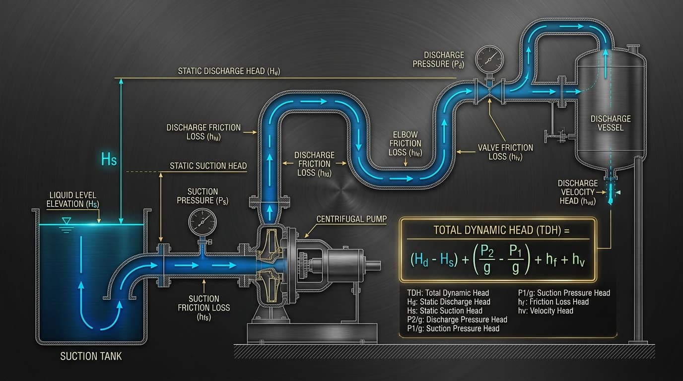
Figure 1: Full hydraulic circuit diagram breakdown for Total Dynamic Head (TDH) showing static lift elevations, vessel pressures, friction losses, and velocity head terms.
Key Takeaway at a Glance
Total Dynamic Head (TDH) is the total equivalent height in meters (or feet) of fluid that a pump must impart to overcome elevation differences, vessel pressure differentials, and friction drag across pipes and fittings at a given volumetric flow rate. Oversizing TDH wastes electricity and pushes the pump to cavitate or overheat, while undersizing leaves your process starved of flow.
1. What is Total Dynamic Head (TDH)? The Plain English Explanation
If you ask a process engineer in a chemical plant or power station what sizing parameter matters most for selecting a pump, they will almost always answer: flow rate (Q) and Total Dynamic Head (TDH).
While flow rate tells you how much fluid needs to move per hour (e.g. cubic meters per hour or gallons per minute), TDH tells you how much mechanical energy per unit weight the pump impeller must impart to that fluid to overcome all physical obstacles along its journey.
Why do we measure pump pressure in "head" (meters or feet of liquid column) instead of bar or PSI? Because a centrifugal pump is a velocity machine. An impeller of a specific diameter rotating at a fixed speed will propel any fluid to the exact same physical column height, regardless of whether that fluid is light kerosene (specific gravity 0.8) or heavy brine (specific gravity 1.2). The pressure gauge reading in PSI will change with liquid density, but the head in meters remains constant!
Calculate Your System TDH in Real Time
Plug in your elevations, pipe lengths, boiler pressures, and flow rates to generate dynamic H-Q curves and motor ratings instantly.
2. The Master TDH Equation Broken Down
Derived directly from the energy balance principle (Bernoulli's Theorem applied between the suction liquid surface and the discharge point), the complete expression for Total Dynamic Head is:
- H_static: Total static elevation difference (Z_discharge - Z_suction) [meters or ft]
- H_pressure: Differential vessel surface pressure converted to fluid column height [(P_discharge - P_suction) / (ρ · g)]
- h_f: Total piping friction head losses + minor valve/fitting losses (h_f,suction + h_f,discharge)
- h_v: Net velocity head differential [(v_discharge^2 - v_suction^2) / (2g)]
3. Static Head vs. Dynamic Head: Why the Difference Matters
Understanding the distinction between Static Head and Dynamic Head is critical when planning variable speed control (VFDs) or predicting pump behavior under throttled conditions:
Static Head (Independent of Flow)
Static head does not change whether fluid is moving at 1 liter per minute or 10,000 liters per minute. It represents the physical vertical lift from the liquid level in the suction tank to the discharge point, plus any fixed pressure difference between closed vessels (like a deaerator at 2 bar feeding a boiler drum at 40 bar). On an H-Q curve graph, static head is the non-zero Y-intercept!
Dynamic Head (Grows Quadratically with Flow)
Dynamic head consists of fluid friction against pipe walls, turbulence around elbows, valves, tees, and strainers, and velocity acceleration. Because fluid drag scales with the square of velocity (h_f ∝ v^2), dynamic head rises parabolically (k · Q^2). Double your flow rate through a pipe, and your friction loss quadruples!
4. Suction vs. Discharge Calculations (Flooded vs. Suction Lift)
A common source of confusion when computing H_static is properly signing the suction elevation depending on the physical tank arrangement:
Case A: Flooded Suction (Liquid Above Pump Centerline)
When the liquid supply vessel is positioned higher than the pump suction nozzle (as in deaerators, overhead tanks, or municipal supply reservoirs), gravity works in your favor. Static suction head is positive and subtracts from the required pump head: H_static = Z_discharge - (+Z_suction).
Case B: Suction Lift (Liquid Below Pump Centerline)
When the pump must pull liquid out of an underground pit, sump, or lower sump tank, the liquid level is below the pump impeller. The pump must expend energy just to lift the liquid up to the nozzle. Static suction head is negative, effectively adding to total required lift: H_static = Z_discharge - (-Z_suction) = Z_discharge + Z_suction.
5. Accounting for Piping Friction & Fitting Losses
In industrial engineering, the most accurate formulation for pipe friction head loss is the Darcy-Weisbach equation, paired with the Colebrook-White equation for turbulent friction factor (f):
For fittings, valves, and elbows, you can either sum their individual resistance coefficients (K-values) or convert each component into an equivalent length of straight pipe (L_eq):
| Piping Fitting / Component | Typical Resistance Coeff (K) | Equivalent Length Ratio (L/D) |
|---|---|---|
| 90° Long Radius Flanged Elbow | 0.30 | 20 |
| 90° Standard Threaded Elbow | 0.75 | 30 |
| Full-Bore Ball Valve (Open) | 0.05 | 3 |
| Globe Valve (Fully Open) | 6.00 | 340 |
| Swing Check Valve (Open) | 2.00 | 100 |
6. Velocity Head: When Does It Actually Count?
Velocity head represents the kinetic energy stored within the moving fluid column, calculated as h_v = v^2 / (2g).
In standard closed-loop heating circuits or when suction and discharge pipes share the same diameter, fluid velocity is equal at both points, making the differential velocity head zero. Even at common industrial velocities of 2.0 m/s (6.5 ft/s), velocity head is only 2.0^2 / (2 × 9.81) = 0.20 meters (0.67 ft). However, when discharging through high-velocity spray nozzles into atmospheric vessels or sizing low-head, high-volume axial pumps, velocity head can account for 10% to 20% of the entire TDH and must not be omitted!
7. Full Worked Engineering Example: Sizing a Transfer Pump
Let us walk through a real-world plant scenario step by step:
Design Specifications:
- Fluid: Industrial Process Water at 30°C (ρ = 996 kg/m³)
- Design Flow Rate (Q): 50 m^3/h (0.0139 m^3/s)
- Suction Liquid Level: Flooded suction +3.0 meters above pump center
- Suction Vessel Pressure: Atmospheric (0 bar(g))
- Discharge Liquid Level: +28.0 meters above pump center
- Discharge Vessel Pressure: Pressurized buffer tank at 2.5 bar(g) (250,000 Pa)
- Calculated Total Suction Friction (h_f,s): 0.4 meters
- Calculated Total Discharge Friction (h_f,d): 5.8 meters
8. 5 Costly TDH Calculation Mistakes to Avoid
1. Adding "just in case" safety margins to every subcomponent
Compounding a 10% margin on pipe length, another 15% on friction, and another 10% on TDH leads to gross oversizing. The pump will operate far out on its curve, causing motor over-amping and cavitation.
2. Confusing Pressure with Head without adjusting for density
A pump generating 100 meters of head produces 9.8 bar with ambient water, but only 7.8 bar with hot thermal oil at 0.8 SG. Always calculate in meters/feet of liquid column first.
3. Forgetting old pipe aging and scale build-up
Using the roughness of brand-new smooth carbon steel (ε = 0.045 mm) for a cooling water line that will corrode and scale over 10 years (ε = 0.15 mm) will cause pump flow starvation within 24 months.
4. Measuring elevation from pump foundation instead of liquid surface
Static head is measured between liquid free surfaces, not pipe centerline or tank nozzle elevation.
5. Neglecting suction strainer blockage differential pressure
Suction basket strainers accumulate debris over time. Failing to include at least 0.2 to 0.5 bar of strainer fouling loss can trigger severe suction cavitation.
9. Frequently Asked Questions (FAQ)
Can TDH be negative in a pumping system?
If the static elevation difference from a high mountain reservoir or elevated tank is greater than all piping friction losses, fluid will gravity-flow freely. In that scenario, no pump is required; a control valve or turbine is needed to dissipate excess energy.
What is the difference between TDH and NPSHa?
TDH measures the total head added by the pump between its suction and discharge nozzles. NPSHa (Net Positive Suction Head Available) measures absolute pressure above vapor pressure exclusively at the pump suction nozzle to prevent vapor bubble boiling.
How does motor speed affect TDH according to affinity laws?
Total dynamic head generated by an impeller scales quadratically with rotational speed (H_2 = H_1 · (N_2 / N_1)^2). Reducing speed by 20% reduces head capability by 36%!
Zylofy Thermal & Fluid Dynamics Engineering Group
Authored and reviewed by certified rotodynamic machinery and power plant hydraulic specialists with decades of EPC engineering experience. Algorithms referenced to ASME BPVC Section I and API 610.