Boiler Feedwater Pump Sizing & Working Principles: Operating Pressures, Deaerators & ASME Standards
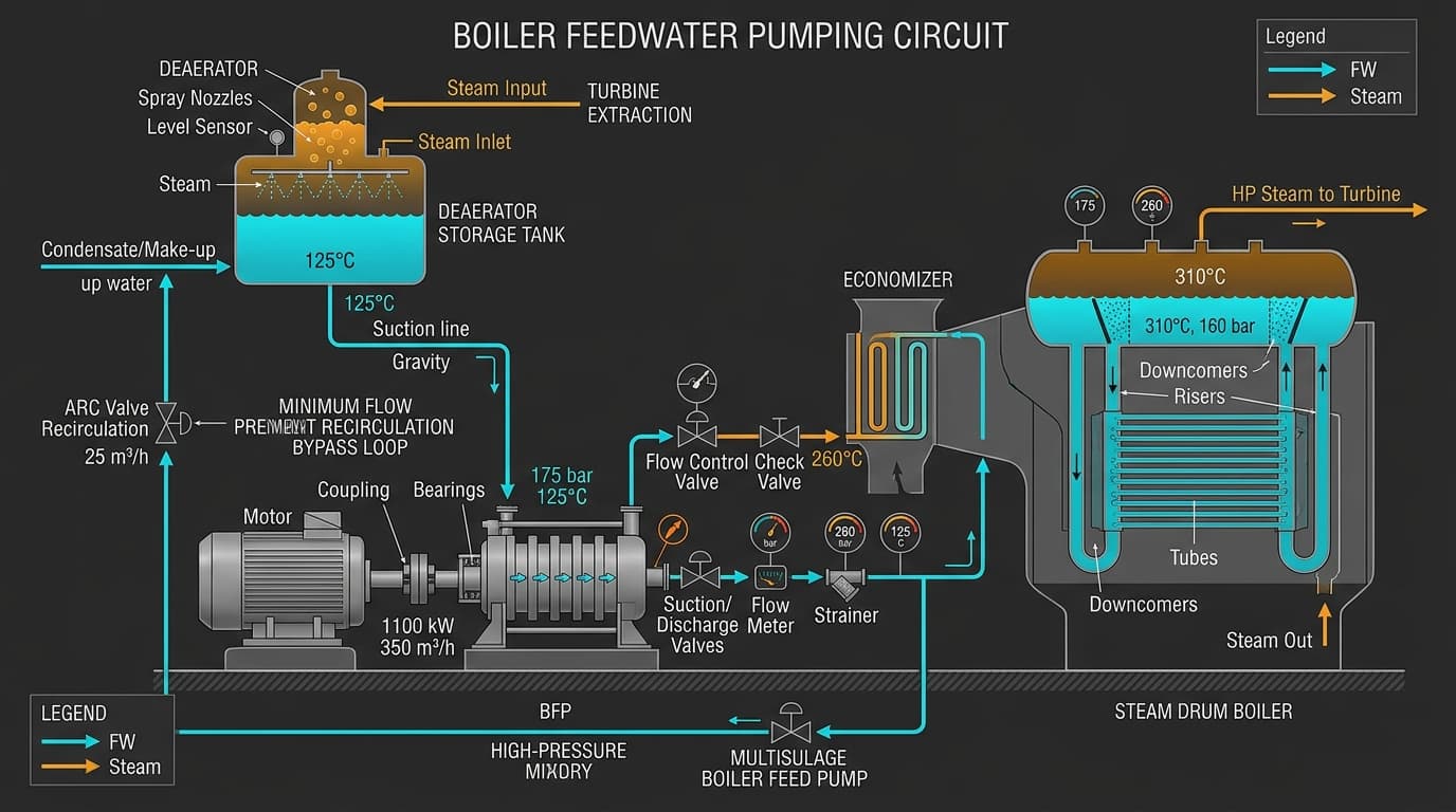
Figure 1: Complete industrial thermal boiler feedwater pumping schematic showing elevated deaerator tank, high-pressure multistage boiler feed pump (BFP), ARC recirculation bypass, and boiler drum feed.
1. Why Boiler Feed Pumps (BFP) Are Safety-Critical
In any steam generation facility—whether powering a combined-cycle utility station, a paper mill, a refinery, or a food processing plant—the Boiler Feedwater Pump (BFP) is the beating heart of the facility.
If a feed pump trips and the standby unit fails to start within 30 to 45 seconds, the boiler drum will starve of liquid. Under extreme furnace temperatures, dry boiler tubes can burst within minutes, leading to catastrophic failure and plant downtime costing millions of dollars. Therefore, ASME BPVC Section I and API 610 dictate strict design, sizing, and redundancy protocols for feed pumping systems.
Size Your Boiler Feed Pump Accurately
Calculate exact mass flow rates, IAPWS-IF97 water properties, and TDH incorporating ASME blowdown and safety factors.
2. The Thermodynamic Foundation: High Temp & Density Shifts
The fundamental trap that ensnares inexperienced sizing engineers is assuming water density is constant at 1,000 kg/m³ (8.34 lb/gal).
In modern plants, feedwater is heated in high-pressure thermal deaerators to temperatures between 105°C and 160°C (220°F to 320°F) to strip dissolved oxygen and carbon dioxide. At 130°C, liquid water expands significantly: its density drops to 934 kg/m³, and its saturation vapor pressure climbs to 2.70 bar absolute.
Because head is inversely proportional to density (H = Δ P / (ρ · g)), delivering 50 bar of pressure with 130°C water requires 546 meters of head, compared to only 510 meters for cold water! Sizing a pump using cold water density will leave your pump 36 meters short of the boiler drum operating pressure!
3. Deaerator Suction Dynamics: Saturated Liquid Behavior
Inside a thermal deaerator, liquid water and heating steam exist at thermodynamic boiling saturation. This means:
When you examine the Net Positive Suction Head Available (NPSHa) formula:
The pressure term [ (P_vessel - P_vapor) / (ρ · g) ] cancels out to zero!
This is why deaerators are always elevated 6 to 15 meters (20 to 50 feet) on structural mezzanines high above the pump foundation.
4. Sizing the Flow Rate: Blowdown & Flow Safety Margins
A boiler feed pump must pump significantly more water than the steam evaporation rating of the boiler. Total required mass flow rate is governed by:
Typical industrial parameters per ASME BPVC Section I:
- Continuous Blowdown: Typically 3% to 5% (up to 10% for poor water quality) to purge dissolved silica, calcium, and mineral salts.
- Flow Safety Factor (SF_flow): Typically 1.10x to 1.25x (10% to 25% margin) to handle rapid steam load swings and 3-element drum level control surges.
5. Sizing Total Dynamic Head: Drum Pressure & Economizers
The required discharge head must overcome not just the boiler drum operating pressure, but all downstream resistance elements:
6. API 610 Classifications: BB3 Axially Split vs. BB5 Barrel Pumps
Between-Bearings, Axially Split Case
Horizontal split along the shaft centerline. Opposed impellers balance hydraulic thrust forces. Ideal for pressures up to 100 bar (1,450 PSI) and temperatures up to 200°C. Easier field maintenance because the top casing unbolts without disturbing piping.
Double-Casing Radially Split (Barrel Pump)
Inner pump cartridge inserted inside a heavy forged steel cylindrical outer barrel. Withstands thermal shocks, rapid cycling, and pressures exceeding 250 bar (3,600 PSI). Standard for supercritical utility power stations.
7. Minimum Flow Protection & Automatic Recirculation Control (ARC)
Because boiler feed pumps develop tremendous head (often 50 to 150 bar), running the pump at shutoff or below minimum flow will convert 100% of motor shaft energy into fluid heat. Inside the pump casing, water temperature can escalate by 50°C in under 20 seconds, flashing into steam and wrecking internal wear rings!
Every BFP must be equipped with an Automatic Recirculation Control (ARC) valve or an active modulated minimum flow control loop that automatically recirculates 20% to 30% of design flow back to the deaerator whenever boiler demand drops.
8. Step-by-Step Numerical Sizing for a 50 Ton/hr Boiler
Specification Inputs:
- Steam Generation: 50,000 kg/h
- Operating Drum Pressure: 40.0 bar(g)
- Deaerator Pressure: 1.5 bar(g) (127.4°C saturation, ρ = 936 kg/m³)
- Blowdown Rate: 4.0%
- Flow Safety Factor: 1.15x
- Head Safety Factor: 1.10x
ṁ = [ 50,000 / (1 - 0.04) ] · 1.15 = 52,083 · 1.15 = 59,896 kg/h
Q = 59,896 kg/h / 936 kg/m³ = 64.0 m³/h (17.78 L/s)
ΔP = (40.0 bar + 2.5 bar economizer + 3.0 bar valve) - 1.5 bar deaerator = 44.0 bar (4.40 MPa)
H = (4,400,000 Pa / (936 · 9.81)) · 1.10 = 479.2 m · 1.10 = 527.1 meters
Hydraulic Power (P_h) = (936 · 9.81 · 0.01778 · 527.1) / 1000 = 86.0 kW
Shaft Power (P_shaft) at 72% pump efficiency = 86.0 / 0.72 = 119.4 kW
Selected Motor: 160 kW (215 HP) 2-pole 2980 RPM Electric Motor
9. Frequently Asked Questions
Why are boiler feed pumps typically multistage?
Generating 500+ meters of head in a single impeller would require enormous tip speeds exceeding 200 m/s, causing severe casing erosion and low efficiency. Multistage pumps split the total head across 6 to 12 successive impellers on a single shaft, keeping tip speeds and stresses within safe metallurgical limits.
What happens during a rapid steam turbine trip?
When a turbine trips, extraction steam to the deaerator stops instantly. Deaerator pressure plunges, but the large body of stored water remains hot. If the pressure drops faster than the water can cool, the water will flash into steam inside the suction line, causing sudden BFP cavitation unless proper transient decay margins are engineered.
Zylofy Thermal & Fluid Dynamics Engineering Group
Authored and reviewed by boiler commissioning engineers, thermodynamicists, and API 610 rotodynamic pump consultants with field experience across industrial and utility power generation plants.