Parallel vs. Series Pump Configurations: Combining System Head Curves & Avoiding Pitfalls
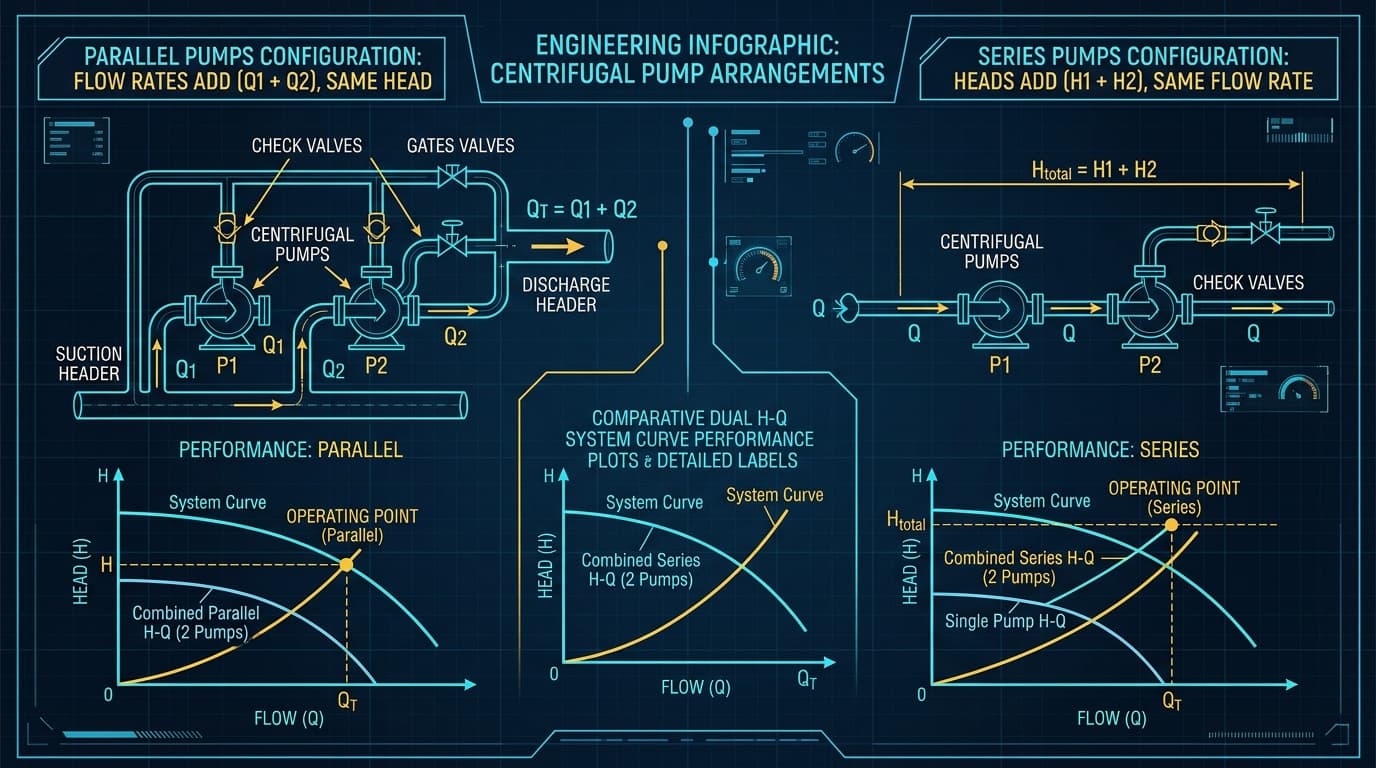
Figure 1: Comparative schematic and H-Q system curves: Parallel configuration adding flow capacity (Q_1 + Q_2) versus series configuration adding total head (H_1 + H_2).
The Golden Hydraulic Rule
When you need more flow rate across a relatively flat system curve, arrange pumps in parallel. When you need to overcome massive vertical lift or high boiler pressure, connect pumps in series. But never operate unmatched pumps in parallel without verifying their shutoff head!
1. The Core Engineering Rule: Flow vs. Head Addition
In industrial facilities, a single pump often cannot satisfy wide operational swings or high pressure demands. Installing multiple smaller pumps provides critical redundancy (N+1 standby), reduces capital expenditure on massive motors, and allows incremental energy modulation during low-demand night shifts.
Parallel Configuration
Pumps draw from a common suction header and discharge into a common discharge manifold. Flow rates add together at each head value (Q_total = Q_1 + Q_2), while the generated head remains identical.
Series Configuration
The discharge nozzle of Pump 1 connects directly into the suction nozzle of Pump 2 (acting as a booster). Heads add together at each flow value (H_total = H_1 + H_2), while fluid flow rate remains identical.
2. Parallel Pumping: Adding Flows at Equal Head
To construct a composite parallel pump curve:
- Select a horizontal head line on the Y-axis (e.g. 40 meters).
- Read the flow rate of Pump 1 (Q_1) and Pump 2 (Q_2) at that head.
- Plot the combined point at (Q_1 + Q_2, 40 m).
- Repeat across all head values from maximum head down to runout.
3. Series Pumping: Adding Heads at Equal Flow
In series pumping, the total volumetric flow travels sequentially through both impellers. To plot the combined series curve:
- Select a vertical flow line on the X-axis (e.g. 100 m³/h).
- Read the head produced by Pump 1 (H_1) and Pump 2 (H_2) at that flow.
- Plot the combined point at (100 m^3/h, H_1 + H_2).
Series arrangements are universally utilized in long overland pipelines, mining slurry lift circuits, and reverse osmosis desalination plants.
4. The Diminishing Returns Law: Why 2 Parallel Pumps Don’t Double Flow
Why does this happen? Because dynamic piping friction losses climb with the square of flow (h_f ∝ Q^2). As flow increases through the shared discharge pipe, system head resistance skyrockets parabolically. The new operating point moves up and to the right on a steeper curve, forcing each pump back toward lower flow and higher head!
5. The Perils of Mismatched Pumps: Deadheading & Valve Slamming
Placing two pumps with different maximum shutoff heads in parallel is one of the most hazardous design errors in process engineering.
If Pump A has a shutoff head of 60 meters and Pump B has a shutoff head of 45 meters, whenever Pump A operates near its high head range (e.g., above 46 meters), the discharge pressure developed by Pump A will slam the check valve of Pump B closed! Pump B will be completely dead-headed, trapped in a zero-flow condition while its motor spins at full speed. Within minutes, the trapped liquid will vaporize, destroying the shaft seal.
6. High Casing Pressures in Series Booster Pumping
When configuring pumps in series, the suction nozzle of the second pump receives the full discharge pressure of the first pump!
Standard ANSI B73.1 process pumps frequently have suction casings rated only for Class 150 (approx 19 bar). If Pump 1 discharges at 15 bar, and Pump 2 develops an additional 15 bar, the casing and mechanical seal chamber of Pump 2 will see 30 bar gauge, blowing standard gaskets. The second pump must be upgraded to API 610 Class 300 or Class 600 heavy-wall flanges with high-pressure balanced mechanical seals.
7. Multi-Pump Skid Control: Staging, Sequencing & Lead-Lag
For optimum energy efficiency in parallel pumping skids:
- Lead-Lag Staging: Run the lead pump on a VFD up to 100% capacity. When flow demand exceeds single pump limits, start the lag pump at base speed while modulating the lead pump to trim flow smoothly without pressure shocks.
- Equal Wear Rotation: Alternate which pump acts as lead unit every 100 operating hours to equalize bearing and seal running hours across the fleet.
- Non-Slam Check Valves: Specify nozzle-style spring-assisted check valves rather than traditional swing checks to eliminate hydraulic water hammer when a lag pump shuts down.
8. Worked Engineering Calculation: Sizing 2 Parallel Process Pumps
System Parameters:
Static Lift: 15.0 meters | System Head Curve: H_sys = 15.0 + 0.002 · Q²
Single Pump Curve: H_pump = 45.0 - 0.0015 · Q²
45.0 - 0.0015 · Q² = 15.0 + 0.002 · Q²
30.0 = 0.0035 · Q² → Q = √(30 / 0.0035) = 92.6 m³/h @ 32.1 m TDH
Combined Curve: At each head H, Q_total = 2 · Q_single
Operating intersection yields: Q_total = 138.8 m³/h @ 42.4 m TDH
9. Frequently Asked Questions
Can you run pumps of different sizes in series?
Yes, as long as both pumps can handle the full system volumetric flow rate. The smaller pump simply acts as a suction booster to raise the pressure before entering the high-pressure main pump.
What is the risk of starting a parallel pump with its discharge valve open?
If the running pump is delivering high discharge pressure, starting an off-line pump with an open discharge valve will force high-pressure fluid backward through the incoming pump, spinning it backward like a turbine and tripping the motor breaker on overcurrent. Always start against a closed valve or verify check valve tight shutoff.
Zylofy Thermal & Fluid Dynamics Engineering Group
Authored and reviewed by pipeline hydraulic consultants and rotodynamic equipment engineers specializing in multi-pump station architecture and transient surge protection.